Portable Power Supplies
Introduction
DIDSA has identified the need for a portable power supply that can be used in future R&D projects. A power supply is viewed by DIDSA as a foundation component that will be included in multiple projects. To avoid work duplication a power supply system will be developed independently, this article can be drawn on later to accelerate future projects.
Safety Considerations
Electrical power supplies and batteries have inherent dangers related to dangerous voltages, risk of fire and explosions. DIDSA recommends that anyone working with the items described here is familiar with these risks and mitigates against them. DIDSA takes no responsibility for the health and safety of anyone replicating this project.
Objectives
The objective of this project is to identify a power supply system for use on future DIDSA projects that fills the following requirements:
- Portable
- Rechargeable
- Scalable in voltage and capacity
- Easily procured and cost effective
Research
To fullfil the requirements the supply will need to include chemical cells. They are split into two categories, primary and secondary. Primary include alkaline and lithium cells which are not rechargeable. Secondary cells are rechargeable the most widely used secondary cell chemistries are:
- Lithium-ion:
- High energy density, long life cycle, low self discharge rate, no memory effect.
- Higher cost, risk of fire, capacity degrades over time, reduced performance at extreme temperatures.
- Lithium-polymer
- Flexible form factor, light weight and very high energy density, safer than Li-ion.
- Shorter life span, higher cost, swelling risk if over charged or damaged.
- Nickel-metal hydride
- Available in standard sizes (AA, AAA, etc), Widely available, Less toxic, High capacity.
- High self discharge, Lower energy density, Some memory effect.
- Lead-acid Battery
- High discharge rate, robust and dependable in harsh conditions.
- Heavy and bulky, shorter life cycle, high self discharge.
Based on the options and their pros and cons, Lithium-ion cells will be selected for the build. To mitigate the safety concerns, a circuit will be utilised to protect against over charge. If a project has specific requirements of the power supply, these can be examined on a case by case basis.
The remainder of this project will focus on 18650 cells which operate at nominal 3.7v. Their use is tremendously widespread and are therefore easy to procure and low cost.
Battery design
Cells
Cells can be connected in series or parallel. Connecting in series accumulates the applied voltage, connecting in parallel accumulated capacity. Thus, a battery should be built that satisfies the requirement of the project.
A certain notation exists to specify the makeup of a battery. The letters S and P are used to denote series or parallel with numbers signifying the number of cells. A 1S1P battery is composed of a single cell. The following table should clarify the notation:
| Notation | Number of Cells | Voltage (Nominal) | Capacity (Based on 2000 mAh Cells) |
|---|---|---|---|
| 1S2P | 2 | 3.7 v | 2000 |
| 2S1P | 2 | 7.4 v | 2000 |
| 2S2P | 4 | 7.4 v | 4000 |
| 3S1P | 3 | 11.1 v | 2000 |
| 3S2P | 6 | 11.1 v | 4000 |
| 3S3P | 9 | 11.1 v | 6000 |
For the purposes of this introductory project, a 1S battery will be build and tested
Charge and Discharge Rate
Two other important metrics for cells are the charge and discharge rates. These specify how quickly a cell can be charged or discharged safely. This is limited by the chemistry of the cell. The method by which these rates are specified is standardised across industry and the C-Rate is defined as follows:
Charge Current (A) = C-Rate x Battery Capacity (Ah)
The C-rate of a battery defines both its maximum safe charge current and its maximum safe discharge current. These are often different, although they are defined by the same equation. It is useful to think of them with respect to the process they govern (charging or discharging).
The charging C-Rate indicates the maximum permissible charging current and therefore the shortest permissible charge time. See below table for examples:
| Charge Rate (C) | Time to Fully Charge when Max Current Applied |
|---|---|
| 0.5C | 2 hrs |
| 1C | 1 hr |
| 2C | 30 min |
| 4C | 15 min |
| 6C | 10 min |
The discharging C-Rate indicates the maximum permissible current to be drawn from the cell. This means that a suitable cell or battery must be selected based on the maximum current draw required by a circuit. For example, a 3000 mAh cell with the following C-Rates can deliver the current shown in the table below:
| Charge Rate (Discharge) | Max Current Draw |
|---|---|
| 0.5C | 1.5 A |
| 1C | 3 A |
| 2C | 6 A |
| 4C | 12 A |
| 6C | 18 A |
A Final Note on C-Rates
When grouping multiple cells in a battery the same equation can be used to find maximum (dis)charging. Pay attention to the effect of parallel and series connection on the capacity of a group of cells. Series connections do not sum capacities, parallel connections do. It should also be noted that grouped cells should share the same C-Rates and capacities. See examples below for clarity, all examples are based on 3000 mAh cells each with a nominal voltage of 3.7V:
| Battery Makeup | Operating Voltage (v) | Capacity (mAh) | C-Rate (Charge) | C-Rate Discharge) | Max Charge Current (A) | Max Current Deliverable (A) |
|---|---|---|---|---|---|---|
| 2P | 3.7 | 6000 | C1 | C4 | 6 | 24 |
| 2S | 7.4 | 3000 | C0.5 | C2 | 1.5 | 6 |
| 2S2P | 7.4 | 6000 | C2 | C6 | 12 | 36 |
| 3S2P | 11.1 | 6000 | C2 | C6 | 12 | 36 |
| 2S3P | 7.4 | 9000 | C2 | C6 | 18 | 54 |
Controller
A small circuit is required to provide the following functions:
- Provide a mechanical connector to charge and discharge the battery.
- Provide over charge protection.
- Provide over discharge protection
- Provide over current (short circuit) protection
- Indicate when the battery is fully charged
To fill these requirements for a single 18650 cell a TP4056 board will be used. This is a single cell Li-ion charging module with an integrated protection circuit. If multiple cells were being used a different circuit would be required. See link and screenshot below for details of the sourced module. It incorporates a USB-C connector for compatibility. An alternative option would be a TP5100 which allows for higher voltage/current and faster charging coupled with better heat dissipation and slightly higher cost. A TP5100 could also support charging 2S battery configuration due to supporting voltages in excess of 8.4v. Where multiple cells are used a Battery Management System must be used to add additional safety features such as cell balancing. Both TP4056 and TP5100 can support parallel pack configurations as these are can be considered as a cell of increasing capacity.
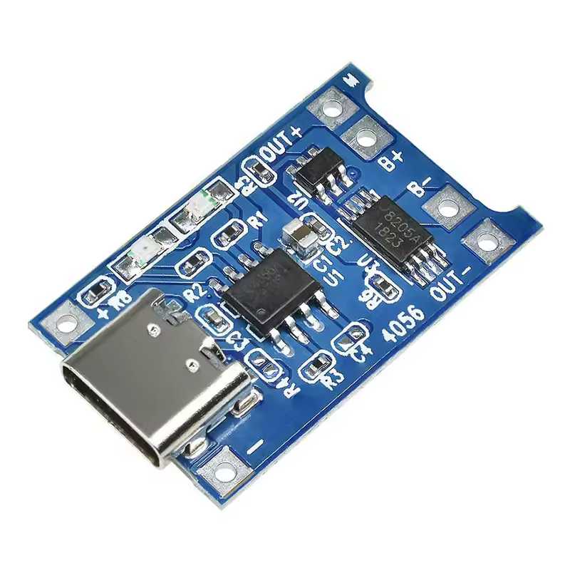
https://a.aliexpress.com/_Ev1gw20/
Circuit Design
The image below shows the design of a single cell 18650 Battery.
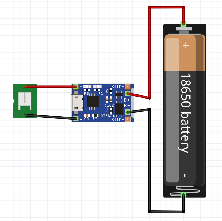
To add support a JST connector will be added. To aid fabrication, a battery holder and perf board will be used. This completes the specification.
The final bill of materials is as follows:
| Description | Qty |
|---|---|
| 18650 Cell | 1 |
| TP4056 Board | 1 |
| 18650 Holder (Single) | 1 |
| Wiring | As Required |
| Perf Board | As Required |
| JST 2.54 1×2 Female Connector | 1 |
Fabrication
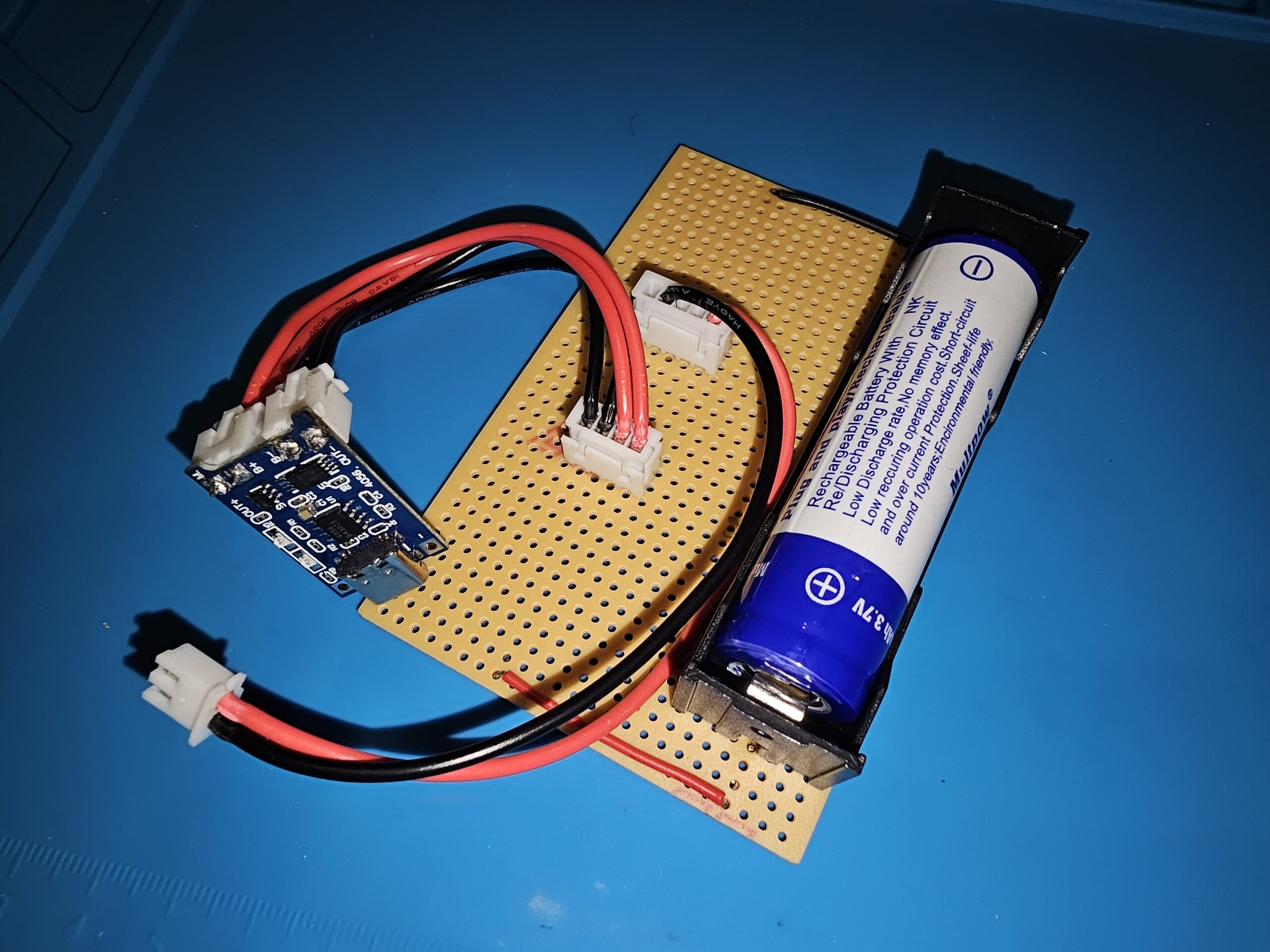
The components are connected as specified using perf board as a mount and soldered connections. See image below for the final result.

The single cell can be charged by connecting a 5v supply to the USB-C port on the TP5046 charging board. An LED on the board indicates charging/charged status. Output is via the JST connector.
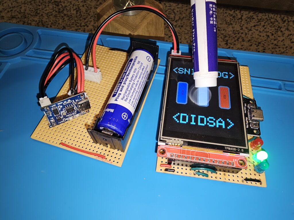
Here the supply is proved by powering another DIDSA project (RED, GREEN, BLUE). This is made up of an ESP32 microcontroller and an LCD panel with touch screen. They operate on 3.3v logic which is within the range of a single 18650 cell.
Conclusion
This exercise has led to the design and build of a single cell power supply. This can be used on experiments going forward. The metrics related to cells and batteries have also been explored and this report will serve as a future reference when more demanding power supplies are required.
The unit built during this project was made from easily procured, low cost items. The cells can be grouped into batteries.
This report can be referenced later to accelerate the process of battery specification, design, manufacture and part procurment. Thus, the scope of the project has been fulfilled.
